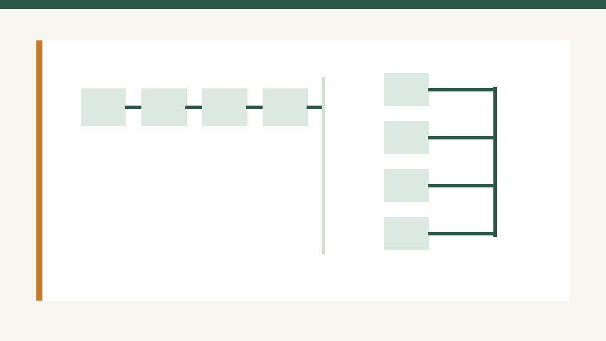
Series and parallel are not competing solar philosophies. They are two electrical operations:
- series adds voltage
- parallel adds current
A useful design starts from the actual module datasheet and the actual charge controller—not from a blanket recommendation that “series is better.”
This guide uses one module consistently: the Canadian Solar CS6.1-54TM-450H. Its published STC values are 450W, 33.0V Vmp, 13.66A Imp, 38.9V Voc, and 14.55A Isc. Canadian Solar also specifies a 25A maximum series fuse rating and a −0.25%/°C Voc temperature coefficient.
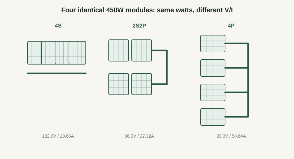
1. One module, three array topologies
For four identical 450W modules:
| Topology | Vmp | Imp | Voc | Isc | STC power |
|---|---|---|---|---|---|
| 4S | 132.0V | 13.66A | 155.6V | 14.55A | 1,800W |
| 2S2P | 66.0V | 27.32A | 77.8V | 29.10A | 1,800W |
| 4P | 33.0V | 54.64A | 38.9V | 58.20A | 1,800W |
The power is nominally the same because:
Topology changes how that power is transported.
2. Worked example A — cable loss over the same circuit
Assume the complete PV positive-and-negative conductor path has 0.10Ω round-trip resistance.
Cable loss is:
| Topology | Current | Voltage drop | Vdrop as % of Vmp | Cable loss |
|---|---|---|---|---|
| 4S | 13.66A | 1.366V | 1.03% | 18.7W |
| 2S2P | 27.32A | 2.732V | 4.14% | 74.6W |
| 4P | 54.64A | 5.464V | 16.56% | 298.6W |
With equal circuit resistance, doubling current multiplies I²R loss by four. Quadrupling current multiplies it by sixteen.
That is the real advantage of higher array voltage: lower current for the same power. It is not permission to ignore controller-voltage limits.
Use the DC Voltage Drop Calculator to replace the illustrative 0.10Ω circuit with your actual cable length and gauge.
3. The controller decides which topology is usable
Before choosing 4S because it has the lowest cable loss, check:
- cold-corrected string Voc
- controller absolute PV voltage
- controller startup/MPPT voltage window
- total PV short-circuit current
- permitted PV power for the battery voltage
For the flagship reference design, four modules in series have:
At −25°C, the module Voc rises using the manufacturer’s −0.25%/°C coefficient:
So:
That is comfortable for the reference 250V-class controller, but the same calculation must be repeated for the actual local design temperature.
4. Worked example B — a topology that is electrically safe but operationally weak
Suppose the same modules are arranged 2S2P on a 51.2V nominal battery.
STC Vmp is:
The reference Victron MPPT requires PV voltage to exceed battery voltage by 5V for startup. The Pytes battery’s published upper voltage range reaches 57.6V, so the controller could need roughly 62.6V just to start at that battery voltage.
A 66V STC array therefore has only a small operating margin before considering hot-module voltage reduction. The topology may satisfy the controller’s maximum-voltage limit and still be a poor match at the low end of the MPPT window.
That is why “below max Voc” is necessary but not sufficient.
5. What partial shade actually changes
Series current is constrained by the electrical behavior of every module in the current path, but modern modules contain bypass diodes. The Canadian Solar reference module specifies three bypass diodes. Shade across one cell group can therefore cause a diode to conduct around that section rather than forcing the entire module to behave as one uniformly shaded block.
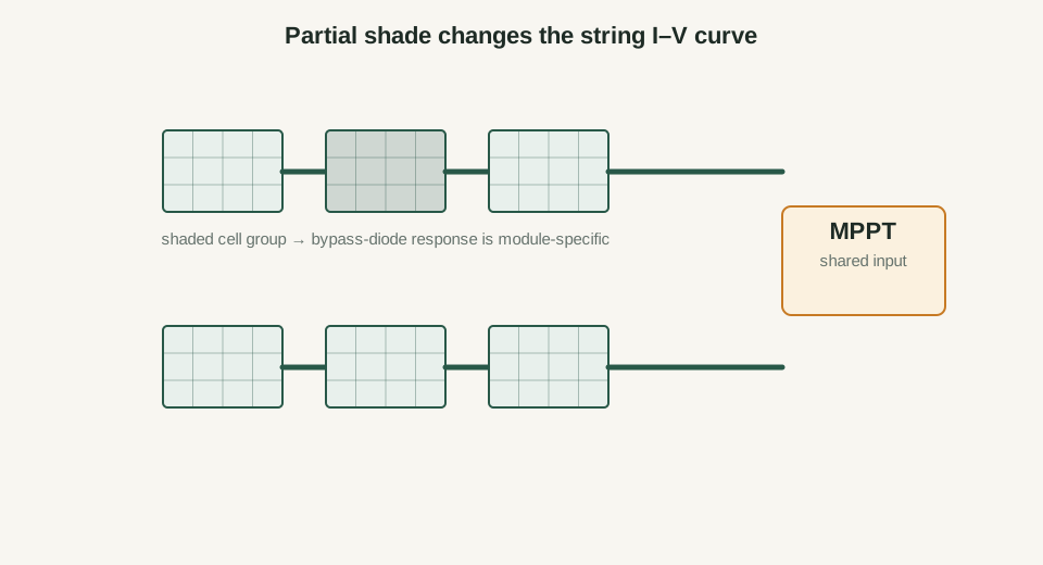
Parallel strings can isolate some mismatch because an unshaded string can continue contributing current independently, but parallel wiring also increases total source current and may change overcurrent-protection requirements.
The better design question is:
Can I avoid the shade, split orientations across separate MPPT trackers, or choose a topology that keeps each tracker electrically coherent?
6. When each topology tends to fit
4S or another longer series string
- long array-to-controller distance
- controller has ample cold-Voc headroom
- battery/controller operating window favors higher PV voltage
- little unavoidable mismatch between modules
2S2P or another series-parallel layout
- controller current and voltage limits allow it
- multiple physical strings fit the site
- orientation/shading layout benefits from separate string paths
All-parallel
- low-voltage controller/application specifically requires it
- cable run is short enough and conductor/protection design handles the current
- module/controller voltage relationship makes series impractical
Do not choose any of these from topology alone. The next step is the MPPT Controller Sizing guide, where the same module and reference controller are checked against cold voltage, operating voltage, current, and PV power.